I love All Electronics, the Van Nuys, CA that buys surplus electronics inventories and offers them to the public at discount prices. One of the items I acquired through them was an assembly from a credit card verification device - it included a circuit board with various ICs (including a DTMF encoder/decoder that I plan to mess with at some point) and a 2-track magnetic stripe reader manufactured by MagTek, Inc. From the datasheet, the interface seemed relatively straight forward: aside from +5v and ground, there were a strobe (clock) and data line for each track, and a common 'card present' line.
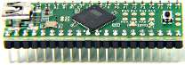
My first attempt was just a simple state machine that would run in an infinite loop looking alternatively for the low and high signals from the strobe line, and then assemble the states of the data lines into 7 bit words (6 bits of data plus a parity bit.) While I was making some progress, I couldn't get any consistent results, and the loops within loops started getting unmanageable. I decided to start over using the built-in interrupts. After some research and fiddling, I was able to create an interrupt that fired every time the clock line changed. The Teensy++ has two types of hardware interrupts - Pin-Change interrupts and External interrupts. The Pin-Change interrupts fire whenever there is a change (low->high or high->low) on the pin. The External interrupts can be set to respond to only low or high change event, and are especially useful in any environment where you have a clocked-in data. Since each type of interrupt is only available on a specific port (or set of pins), and I didn't feel like rewiring my breadboard, I used the Pin-Change interrupts on Port B, and just ignored the changes I didn't need to use.
ISR(PCINT0_vect) {

   //
   // This is the pin-change interrupt that is executed from the STROBE pin
   //

   cli();

   if (STB_LOW) {

      if (start || (!start && DAT_LOW)) {

         if (!start) {start=1;}

         if (DAT_LOW) {
            // 1
            data[i] |=128;
         } else {
            // 0
            data[i] &=~128;
//          parity=(~parity&1);
         }

         bc++;
         if (bc==7) {
            data[i]>>=1;
//          data[i]|=(parity<<7);
//          parity=1;
            bc=0;
            i++;
         } else {
            data[i]>>=1;
         }


      }


   }

   sei();

}
That code initialized the interrupts the Teensy++ needs to respond to, along with the function that handles the interrupt. It fires whenever there is a Pin Change on the pins we initialized the interrupt with. The rest of the code is an infinite loop that process the data from the interrupt once the card present line goes from low to high, performs a Longitudinal Redundancy Check on the data, then outputs it to debug program (available from ___'s website) via USB.
If I would need to implement this again, I would do it using more interrupts; the series of infinite loops is kinda a kludgey way to do it and was meant more as a proof-of-concept project. All in all I learned a lot from this project and look forward to my next and most ambitious one yet - a 240x64 LCD display with controller chip. My full code for the card reader is below:
//
// Notes
//
// Initally integrated parity, but removed since LRC has been implemented
//
//
//  B3 - card present
//  B2 - strobe
//  B1 - data
//
// ToDo: bi-directional scanning: if fails LRC, try reversing bits and repeat

//

#include <avr/io.h>
#include <util/delay.h>
#include <avr/interrupt.h>
#include "print.h"
#include "usb_debug_only.h"

#define CPU_PRESCALE(n)    (CLKPR = 0x80, CLKPR = (n))

#define CP_LOW ((PINB & (1<<3))==0)
#define STB_LOW ((PINB & (1<<2))==0)
#define DAT_LOW ((PINB & (1<<1))==0)

#define LED_ON       (PORTD &= ~(1<<6))
#define LED_OFF   (PORTD |= (1<<6))

unsigned int bc=0;
unsigned int i=0,n=0;
char data[250]={};
char start=0;
char lrc;
char parity=1;
unsigned int decode_mode;


ISR(PCINT0_vect) {

   //
   // This is the pin-change interrupt that is executed from the STROBE pin
   //

   cli();

   if (STB_LOW) {

      if (start || (!start && DAT_LOW)) {

         if (!start) {start=1;}

         if (DAT_LOW) {
            // 1
            data[i] |=128;
         } else {
            // 0
            data[i] &=~128;
//          parity=(~parity&1);
         }

         bc++;
         if (bc==7) {
            data[i]>>=1;
//          data[i]|=(parity<<7);
//          parity=1;
            bc=0;
            i++;
         } else {
            data[i]>>=1;
         }


      }


   }

   sei();

}

int main(void) {

   unsigned int dstart,dend;


    CPU_PRESCALE(0);

   usb_init();

   DDRD |= (1<<6);


   LED_ON;
   _delay_ms(1000);
   LED_OFF;

   // B3 Card Present, B2 Strobe, B1 Data

   DDRB &= ~(1<<3);
   DDRB &= ~(1<<2);
   DDRB &= ~(1<<1);

   // Set interrupts

   PCMSK0 |= (1<<PCINT2); // PORT B2
   PCICR |=(1<<0);  // Enable pin external interrupts
   sei();  // Turn on interrupts

   while (1) {

      while (!CP_LOW) {}
      while (CP_LOW) {}

      // LRC

      decode_mode=0;

      for (n=0;n<160;n++) {

         if (decode_mode==0) {

            if ((data[n]&63)==5) {
               decode_mode=1;
               dstart=n+1;
               lrc=5;
            }

         } else if (decode_mode==1) {

            lrc^=(data[n]&63);

            if ((data[n]&63)==31) {
               dend=n-1;
               decode_mode=2;
            }

         } else if (decode_mode==2) {

            lrc^=(data[n]&63);
            decode_mode=3;

         }

      }
      lrc&=63;

      // Output data iva USB Debug

      if (!lrc && decode_mode==3) {

         print("Data received.\n");
         for (n=dstart;n<=dend;n++) {

            pchar((data[n]&63)+32);

         }
         print("\n\n");

      } else {

         print("LRC error - rescan\n\n");

      }

      bc=0;
      i=0;
      start=0;
      parity=1;
   }


   return 0;

}